Busbar insulators support conductive busbars while maintaining electrical separation from grounded panels, adjacent phases, and other metal components. In switchgear, distribution cabinets, control panels, renewable-energy equipment, and industrial power systems, they must provide both dielectric insulation and mechanical stability.
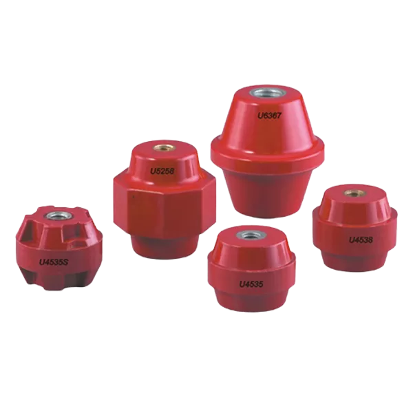
A suitable insulator is therefore not selected by colour or height alone. Engineers and buyers need to compare the product structure, moulding material, withstand voltage, mechanical strength, thread configuration, installation environment, and busbar arrangement. EASCO currently offers multiple busbar insulator types, including U, TSM, S, SM, SEP, SB, MNS, ID, EN, D, C, 71, CL, EL, L, and step-type series.
A busbar insulator performs two functions at the same time.
First, it keeps an energized copper or aluminium busbar electrically separated from the enclosure, mounting plate, nearby conductors, and grounded components. Second, it supports the busbar against its own weight, installation stress, vibration, thermal expansion, and electromagnetic forces during fault conditions.
This combination distinguishes a busbar support insulator from a simple plastic spacer. The component must maintain its shape and insulation properties throughout the expected operating life of the electrical assembly.
Its performance affects:
Phase-to-phase and phase-to-ground clearance
Busbar alignment
Mechanical rigidity
Resistance to electrical arcing
Short-circuit stability
Maintenance access
Long-term equipment reliability
A product with adequate dielectric strength but insufficient mechanical capacity may crack or loosen. A mechanically strong support with inadequate creepage or clearance may still create an insulation risk.
The differences between busbar insulator types are usually related to body shape, mounting method, support height, insert configuration, and the number of busbars supported.
Post-style products are widely used to raise a single busbar above a mounting panel. They are commonly found in low- and medium-voltage switchgear, power-distribution cabinets, battery systems, and industrial control equipment.
These insulators may have round, cylindrical, ribbed, or hexagonal bodies. Their compact form makes them suitable for straightforward busbar layouts where each support carries one conductor or one stacked conductor group.
EASCO’s U, TSM, S, SM, SEP, and SB families are examples of product series used for different mounting dimensions and performance requirements.
A hexagonal body gives installers a flat surface that can be held with a suitable tool during assembly. This can make positioning and fastening easier than with a fully round body.
Hexagonal supports are useful where:
Assembly access is limited
Precise alignment is important
The insulator may rotate during tightening
A compact mounting footprint is required
The body shape itself does not determine the electrical rating. Buyers must still compare the relevant material, height, thread, and test data.
Ribbed profiles increase the surface path between conductive parts. This can support improved creepage performance within a compact overall height.
They may be useful in equipment exposed to higher humidity, surface contamination, or more demanding insulation requirements. However, the exact creepage distance and withstand performance should be confirmed from the technical specification rather than inferred from appearance.
Step-type products support several conductors at controlled positions or different levels. They are useful in multi-phase assemblies and compact power-distribution systems where separate post insulators would occupy too much space.
EASCO lists a dedicated Step Type Bus Bar Insulator category alongside its individual post-style series.
A step configuration can help maintain consistent conductor spacing, but the model must match the actual bar thickness, phase arrangement, mounting pattern, and required electrical separation.
Busbar insulators are commonly produced from moulded thermosetting compounds because these materials can combine electrical insulation, heat resistance, dimensional stability, and mechanical strength.
Bulk Moulding Compound is frequently used for industrial insulating components. Depending on the formulation, it can provide:
Reliable dielectric performance
Good dimensional stability
Flame resistance
Resistance to heat and moisture
Efficient high-volume moulding
Consistent finished dimensions
BMC is suitable for many standard switchgear and panel applications, provided the specific product rating matches the electrical and mechanical requirements.
Sheet Moulding Compound is also used for high-strength electrical parts. Compared with general-purpose moulding compounds, an appropriate SMC formulation may offer higher structural performance and good stability under demanding operating conditions.
It is often considered where the component must tolerate:
Greater mechanical stress
Temperature cycling
Vibration
Larger conductor loads
More demanding equipment environments
The terms BMC and SMC describe material families rather than one fixed performance level. Buyers should request the technical data for the actual model being supplied.
EASCO states that its insulator range uses flame-retardant materials and is designed for dielectric strength, thermal stability, and resistance to moisture, chemicals, and UV exposure.
| Selection factor | BMC insulator | SMC insulator |
|---|---|---|
| Electrical insulation | Suitable for a wide range of industrial applications | Suitable for demanding electrical applications |
| Mechanical performance | Good for standard support requirements | Often selected where higher structural strength is needed |
| Dimensional consistency | Good when correctly moulded | Good for larger or structurally demanding components |
| Heat resistance | Depends on the formulation and model | Depends on the formulation and model |
| Typical use | Distribution panels, control cabinets and standard switchgear | Higher-load assemblies and demanding power equipment |
| Final selection basis | Model-specific test data | Model-specific test data |
This comparison should be treated as a sourcing guide rather than a universal material rule. Voltage, strength, temperature, and flame performance must be verified for each part number.
Technical selection should begin with the busbar system and then move to the insulator specification.
| Parameter | Why it matters |
|---|---|
| Overall height | Controls the distance between the busbar and mounting surface |
| Body diameter or width | Affects mechanical stability and installation space |
| Thread size | Determines fastener compatibility |
| Thread depth | Prevents insufficient engagement or fastener bottoming |
| Insert material | Influences fastening strength and corrosion compatibility |
| Withstand voltage | Indicates the insulation level under test conditions |
| Creepage distance | Influences surface insulation performance |
| Clearance distance | Helps maintain safe separation through air |
| Tensile strength | Indicates resistance to pulling loads |
| Bending strength | Important for long bars and fault forces |
| Torque limit | Prevents damage to the insert or moulded body |
| Temperature range | Must cover actual equipment operating conditions |
| Flame performance | Important for cabinet and switchgear safety |
A catalogue dimension cannot replace these values. Two products with a similar height and thread may perform differently under electrical or mechanical stress.
Insulator height influences both electrical clearance and mechanical leverage.
A taller electrical bus bar insulator can provide more distance between the live conductor and the metal backplate. It may also create more space for cable lugs, protective covers, airflow, and maintenance tools.
However, increasing height also increases the leverage applied to the support when the busbar moves sideways. This can raise bending stress during vibration, transportation, thermal expansion, or short-circuit events.
A shorter support creates a more compact and mechanically rigid assembly but may not provide the required phase-to-ground distance.
The correct height must therefore balance:
System voltage
Required clearance
Panel depth
Busbar dimensions
Fault-current forces
Support spacing
Access for assembly and maintenance
Busbar insulators are used wherever rigid conductors must distribute current safely within an electrical system.
In distribution boards and switchgear, insulators hold the busbars at fixed distances from grounded metal structures and from one another. Their positioning affects both insulation safety and the mechanical response of the assembly during a fault.
A panel busbar insulator may support the main incoming supply, internal power-distribution bars, neutral conductors, or earth bars. Proper support makes the layout more stable and reduces unwanted conductor movement. EASCO identifies industrial control panels as one of the main application areas for these products.
Solar inverters, battery-energy-storage equipment, converters, and wind-power control systems use busbars to handle high current in compact assemblies. Insulator selection must account for temperature, current-related heating, vibration, and the conductor layout.
Transport systems can expose electrical components to vibration, dust, moisture, temperature cycling, and restricted installation space. The support system must therefore maintain both electrical separation and mechanical stability.
EASCO also lists power distribution, renewable energy, and railway or transportation systems among the application areas for busbar insulators.
Busbar insulator damage is often caused by installation or system conditions rather than normal electrical loading alone.
Common causes include:
Excessive tightening torque
Fasteners with incorrect thread engagement
Misaligned busbars pulled into position by bolts
Excessive distance between support points
Fault-current forces
Impact during assembly or transportation
Persistent overheating
Dust and conductive contamination
Moisture and condensation
Cracks caused by ageing or mechanical stress
A busbar should rest naturally on its supports before final tightening. Using fasteners to force a warped or misaligned bar into position transfers continuous stress into the insulating body.
Damaged supports may show cracks, looseness, carbonisation, surface tracking, discolouration, or deformation. EASCO’s article on insulator faults discusses inspection and handling of physical damage and operating abnormalities.
There is no single support spacing suitable for every busbar system.
The correct distance depends on:
Busbar width and thickness
Copper or aluminium construction
Current and temperature rise
Orientation of the bar
Number of bars in the stack
Fault-current level
Insulator strength
Equipment vibration
Applicable design standards
Increasing the spacing reduces the number of supports but raises busbar deflection and mechanical load at each point. Closer spacing improves rigidity but increases cost and installation complexity.
For fault-sensitive systems, support spacing should be validated as part of the complete busbar assembly rather than estimated from normal conductor weight alone.
A professional request for quotation should identify:
Required series or body structure
Overall height
Body diameter or width
Upper and lower thread
Thread depth
Insert material
Insulating material
Voltage or proof-voltage requirement
Mechanical-strength requirement
Torque limit
Operating-temperature range
Colour
Quantity
Required compliance documents
Customisation requirements
Keywords such as busbar insulator manufacturers, busbar insulator suppliers, or busbar support insulator manufacturer may lead buyers to the correct product category, but they do not define the technical requirement.
The drawing, ratings, and actual application should always accompany the inquiry. EASCO’s product category includes numerous series and structural options, so providing complete parameters helps the supplier narrow the selection efficiently.
The terms are often used for similar support components in online searches and international sourcing. In a technical specification, “busbar insulator” or “busbar support insulator” is generally clearer because the product both supports and electrically insulates the conductor.
Only when its electrical ratings, dimensions, creepage, clearance, and mechanical performance satisfy each system. Physical compatibility alone is not enough.
Red is a common moulded-product colour and may improve component visibility, but colour does not establish the voltage rating, material, or mechanical strength.
Manufacturers may support custom dimensions, inserts, colours, threads, or moulded structures, depending on quantity and tooling requirements. Buyers should provide a drawing and complete performance specification.
Replace a unit showing cracks, looseness, carbonisation, electrical tracking, heat damage, insert movement, or significant deformation. The cause of the damage should be corrected before installing the replacement.
Busbar insulators are compact components with a direct influence on the electrical safety and mechanical stability of a power-distribution system.
Product type determines how the conductor is positioned and supported. Material affects dielectric, thermal, and structural performance. Height, thread, insert design, creepage, withstand voltage, and mechanical strength determine whether the insulator is suitable for the actual assembly.
For switchgear manufacturers, panel builders, renewable-energy equipment suppliers, and industrial buyers, the best results come from comparing complete technical data rather than choosing an insulator by appearance. Working with qualified busbar insulator suppliers and providing a clear application specification helps reduce mounting errors, improve busbar stability, and support reliable long-term operation.