Correct wiring duct installation depends on four fundamentals: selecting enough usable capacity, positioning the duct around the actual terminal layout, making clean cuts, and routing conductors without forcing them against the fingers or cover.
Most installation failures do not begin with a defective duct. They usually result from undersized channels, poor mounting, unsuitable slot geometry, excessive cable crossings, or covers being forced over an overloaded wire bundle. These problems may not be obvious when a panel is first assembled, but they can make troubleshooting, circuit expansion, and routine maintenance unnecessarily difficult.
The following seven mistakes are among the most common causes of damaged cable insulation, loose covers, and inefficient control-panel wiring.
The nominal width and height of a duct do not represent its complete usable capacity. Wall thickness, finger geometry, cover engagement, internal dividers, and cable crossings all reduce the space available for conductors.
Before choosing an electrical wiring duct, installers should calculate the approximate cable load and consider:
The outside diameter of each conductor
Cable markers, ferrules, and insulation sleeves
Shielded or multi-core cable thickness
Required cable bend radius
Space occupied by dividers and retainers
Wire crossings within the channel
Future additions to the control panel
A duct should not be filled until the cover presses against the wires. Technicians must still be able to trace, lift, and replace an individual conductor without removing most of the bundle.
Underestimating future expansion is especially costly. A control panel may later require additional sensors, relays, communication modules, or safety circuits. Leaving practical spare capacity is usually more economical than replacing the complete ducting system during an upgrade.
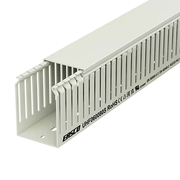
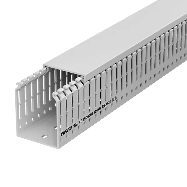
Slot width and finger spacing should match both cable diameter and terminal density.
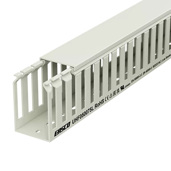
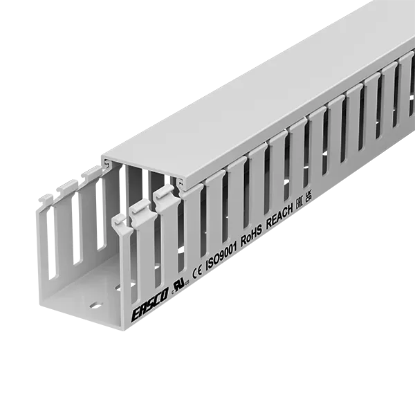
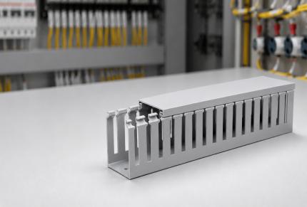
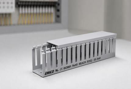
Narrow-slot ducts provide more exit positions and are often suitable for closely spaced terminal blocks, PLC input and output modules, instrumentation circuits, and small control wires. Wide-slot ducts allow larger cables or grouped conductors to leave the channel more easily.
A slotted PVC cable duct should also be evaluated for:
Finger rigidity
Finger breakability
Slot-edge smoothness
Cover-retention design
Consistency of slot spacing
Selecting a wide-slot profile for many small conductors can reduce support between exit points. Conversely, forcing thick cables through narrow slots may stress the insulation and deform the fingers.
The best slot design is not necessarily the design with the largest openings. It is the one that allows conductors to leave the duct close to their terminals without sharp bends or unnecessarily long exposed wire sections.
Overfilling is one of the main reasons a wiring duct cover repeatedly becomes loose.
When the wire bundle rises above the side walls, it pushes upward against the cover. The cover may appear secure immediately after installation but gradually release because of cable pressure, vibration, or temperature changes.
Other signs of overfilling include:
The cover requires excessive force to install
Fingers spread outward when the cables are inserted
Wires are compressed against one another
Individual conductors cannot be removed easily
The cover lifts near cable crossings
Cable labels become hidden inside the bundle
A larger PVC cable duct or an additional parallel route should be considered when the existing channel cannot hold the wiring comfortably.
Installers should not solve an overfilling problem by adding tape, cable ties, or external clips around the cover. These measures hide the underlying capacity problem and make later access more difficult.
Poor cutting can leave sharp burrs, cracked fingers, uneven ends, and distorted cover rails. Each of these defects can damage cable insulation or prevent adjacent duct sections from aligning correctly.
A dedicated duct cutter or a fine-tooth saw is normally preferable to a coarse blade. After cutting, installers should check that:
The cut is square.
Loose plastic fragments have been removed.
No sharp edge remains near the wire path.
The side walls have not been compressed.
The cover still engages properly.
Cutting several fingers at once with pliers can create an irregular cable opening. Where a larger exit is required, finger-breakable duct should be broken at the designed points or trimmed carefully with an appropriate tool.
This step is particularly important with a cable duct slotted profile because cables pass directly between the cut fingers. Even a small burr can scrape insulation whenever a wire is installed or repositioned.
A straight duct can become twisted when it is fastened to an uneven panel surface. Once the side walls are distorted, the cover may engage on one section but remain loose on another.
Before installation, the mounting surface should be clean, dry, and free from metal chips, raised fasteners, oil, or debris. Mechanical fasteners should be tightened sufficiently to secure the base without deforming it.
The fixing method must also reflect the application. Adhesive mounting may be suitable for certain lightweight, low-temperature installations, but mechanical fastening is generally more dependable in panels exposed to:
Continuous vibration
Elevated temperature
Heavy cable loads
Transportation shock
Frequent maintenance
Oil or surface contamination
Pre-punched mounting holes can improve installation consistency, but fastener spacing should still prevent the duct from lifting between fixing points. EASCO’s wiring ducts include products with snap-on covers and prepared mounting options intended to simplify panel assembly.
A well-organized duct is ineffective when wires must make sharp turns immediately after leaving it.
Duct positioning should be planned together with DIN rails, terminal blocks, circuit breakers, contactors, drives, and cable-entry points. Each wire should leave the slot in the direction of its terminal rather than bending back across the duct wall.
Common layout errors include:
Installing the duct above equipment whose terminals face downward
Placing it too close to a terminal row
Creating tight 90-degree cable turns
Crossing several cable groups at one point
Leaving long unsupported wire sections outside the duct
The required bend radius depends on conductor construction and cable type. Larger power cables, shielded cables, and multi-core cables generally need more turning space than small control wires.
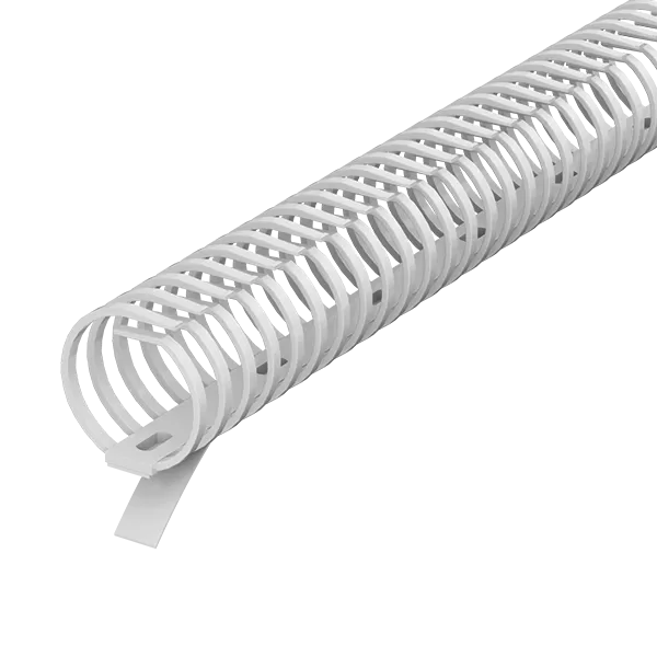
Flexible routes should not be forced into a rigid rectangular duct. A flexible wiring duct is more suitable for cabinet doors, moving assemblies, curved routes, or areas where repeated flexing may occur.
The duct itself is only one part of the cable-management system. Correct accessories help keep conductors in place during assembly, transport, and maintenance.
A cover must correspond to the exact duct profile. A similar-looking cover from another series may fit loosely, engage unevenly, or require excessive force. It is also important to check that cut covers align with the duct ends and do not leave raised edges.
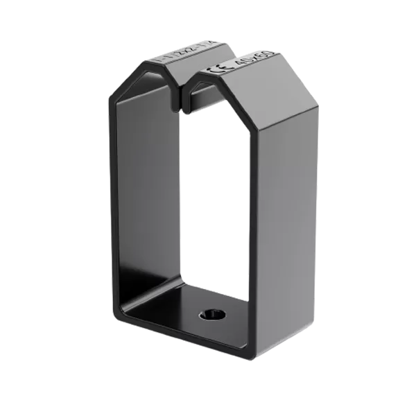
Dividers may be used to organize separate cable groups within a wider channel, while wire retainers can prevent cables from falling out before the cover is installed. Relevant wiring duct accessories should therefore be specified during the initial order rather than added after the panel has already been wired.
However, a divider does not automatically make it acceptable to place any power and signal cables together. Voltage, electromagnetic interference, shielding, grounding, and applicable electrical requirements must still be reviewed.
The most common causes are excessive cable fill, a mismatched cover, distorted side walls, poor mounting, and deformation caused by temperature or impact.
Begin by removing the cover and checking whether any conductor rises above the duct walls. Then inspect the complete channel for twisting, cracked engagement rails, uneven cuts, or loose mounting screws.
Replacing the cover alone will not correct a duct that is overloaded or deformed. The cable arrangement or duct capacity must first be corrected.
Power and sensitive signal cables should be separated when required by the electrical design, equipment instructions, or applicable standards. Separate ducts are often preferable when high-current conductors run close to communication, encoder, sensor, or data cables.
Where the installation has stricter fire and smoke requirements, material selection must also be reviewed. A low smoke duct may be more appropriate in rail transport, public infrastructure, marine equipment, or other enclosed environments where smoke density and corrosive emissions are important.
Before energizing the panel, confirm that:
All duct sections are mounted securely
Cuts and cable exits are smooth
Covers engage along their full length
Wires remain below the side walls
Bend-radius requirements are maintained
Power and signal circuits are appropriately arranged
No conductor is trapped beneath a cover edge
Labels remain visible
Space is available for reasonable future additions
Wiring duct installation should make a control panel easier to assemble, inspect, and modify. Correct sizing, slot selection, cutting, fastening, and cable routing prevent most cover and insulation problems before they occur. A duct that closes without force and allows individual wires to remain accessible is usually a better indicator of installation quality than appearance alone.